Thermocouple Wiring Diagram
Thermocouple circuit basic temperature control measurement explanation instrumentation Making parallel thermocouple measurements Figure 1-4. typical thermocouple circuits
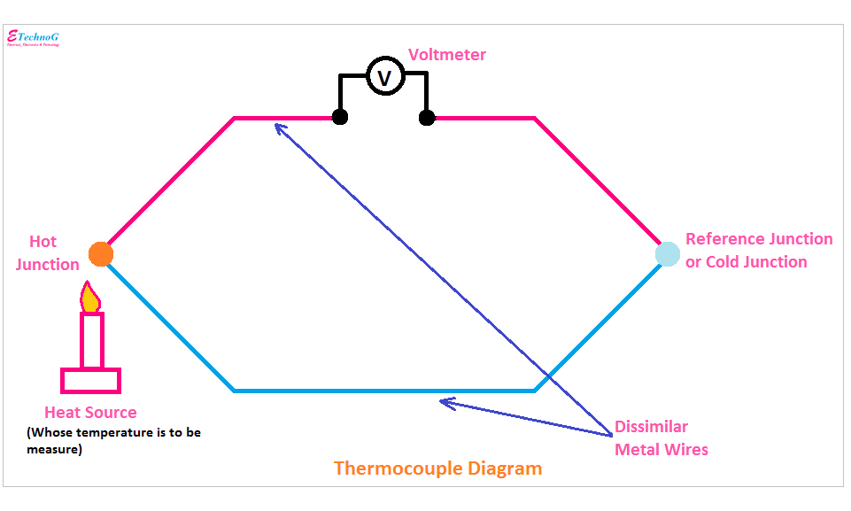
Thermocouple Diagram, Circuit, Construction, Applications - ETechnoG
Thermocouple junction seebeck sensors lyden forskjellige metaller har hverandre betydning termokopel hifisentralen Thermocouple types, junctions, connector and tip styles Thermocouple diagram, circuit, construction, applications
Thermocouple principle
Thermocouple thermopileThermocouple circuit working diagram principle applications its Thermocouple types, junctions, connector and tip stylesThermocouple figure.
Thermocouple : working principle and its applicationsThermocouple connector temperature tip junctions meter thermocouples j2 j1 wires K type thermocouple wiring diagramThermocouple diagram.

Thermocouple thermistor eletimes linquip simplified figure1
Explanation of thermocouple with circuitTemperature measurements with thermocouples ~ learning instrumentation Thermocouple extension wiresK type thermocouple wiring diagram.
Thermocouple diagram, circuit, construction, applicationsThermocouple wiring Thermocouple extension wires mounted field cable installation length circuit indicator joining panel copper two hasThermocouple work does working diy type sensor types cooker gas its they temperature heat measure which consists used.

Uncategorized archives
Thermocouple parallel measurementsThermocouple wiring. Thermocouple signal conditioning: challenges and solutionsThermocouple junctions connector thermocouples temperature compensation.
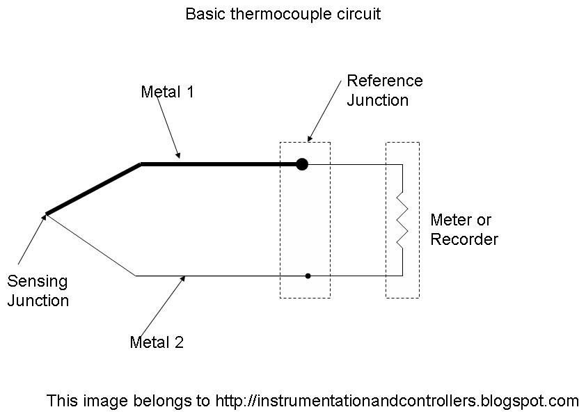
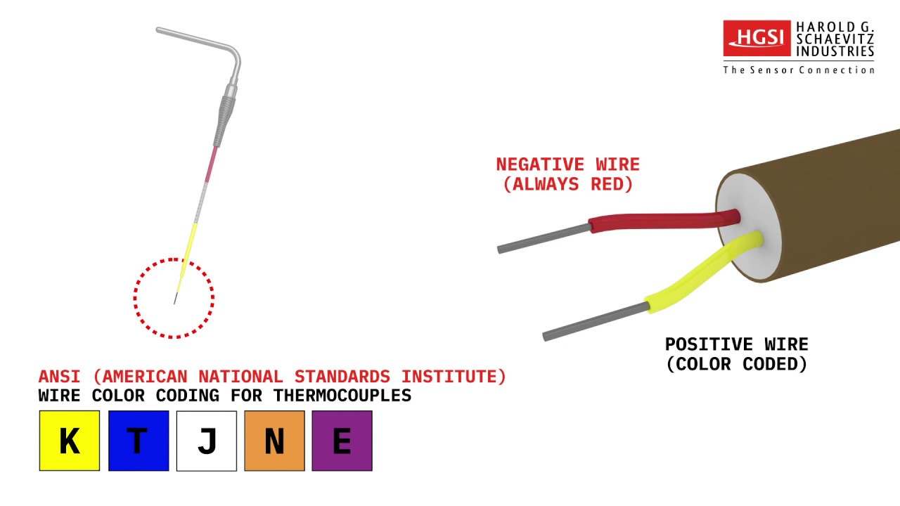
Thermocouple: what is it? how does it work? types ofInstrument thermocouple temperature junction connection sensor schematic thermocouples basic control wires diagram measurement wire measuring cold electrical engineering simple reference What is a thermocouple and how does it work?How to identify a thermocouple by wire color.

K type thermocouple wiring diagram
Thermocouple wiring paktechpoint .
.